【FEATURES】 | 【APPLICATIONS】 |
※ High Performance | ※ Communication System |
※ Low VSWR | ※ Radar System |
※ Full bandwidth of the waveguide | ※ Microwave Measurement System |
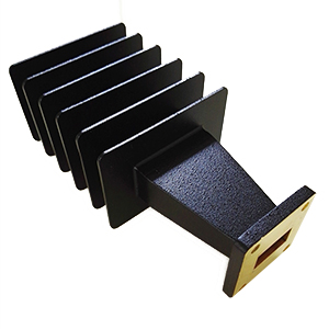
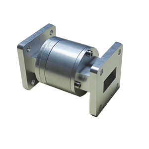
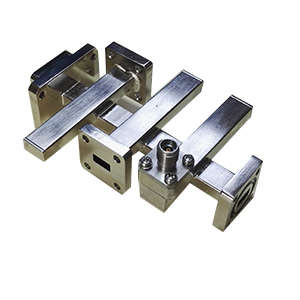
Crossguide Directional Coupler |
【PRODUCT TYPE】
Code | Description | Code | Description |
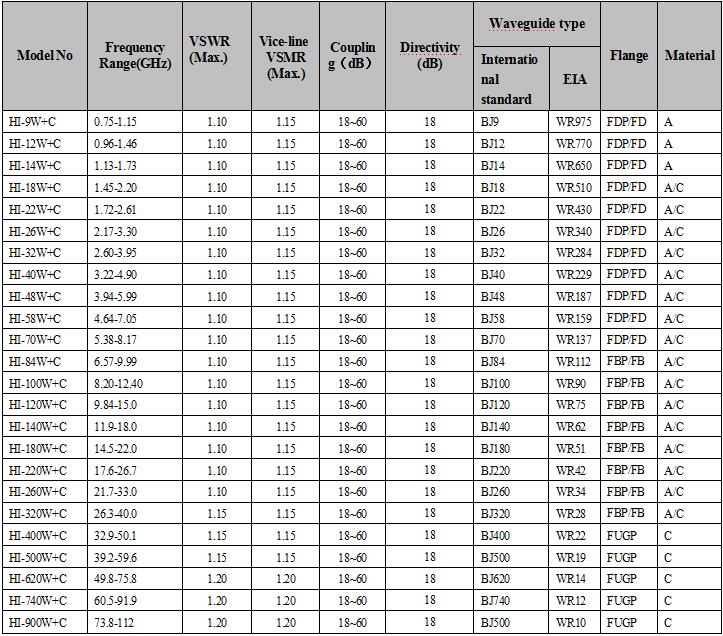
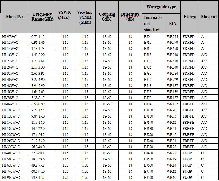
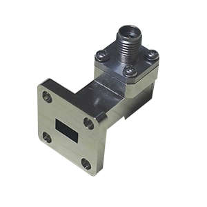
W+C | Rectangular waveguide cross coupler (four port waveguide output) | WL+C | Rectangular waveguide cross coupler (waveguide output, load built in)) |
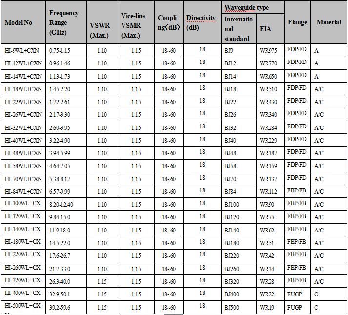
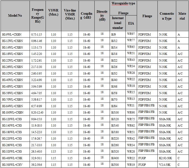
WL+C…N | Rectangular waveguide cross coupling (coaxial connector output, load built in) | WL+C…BN | Rectangular waveguide cross coupling (coaxial connector output, load built in) |
Coaxial connector type
N=N-K NJ=N-J S=SMA-K SJ=SMA-J TNC=TNC-K TNCJ=TNC-J
BNC=BNC-K BNCJ=BNC-J K=K2.92-K KJ=k2.92-J V=V2.4-K VJ=V2.4-J L16=L16-K L16J=L16-J L29=L29-K L29J=L29-J
Flange Type: Standard rectangular waveguide coaxial converter common flange type table.
Waveguide Model | P | M | E | U |
BJ3 ~ BJ70 | FDP | FDM | / | / |
BJ84 ~ BJ320 | FBP | FBM | FBE | / |
BJ400 ~ BJ500 | / | / |
| FUGP |
Material: A=Aluminum B=Brass C=Copper
HI-W+C series waveguide cross coupler
【DATA SHEET】
HIL + C series waveguide cross coupler
HI-WL+C…N series waveguide cross coupler
HI-WL+C…BN series waveguide cross coupler
Waveguide High Directivity Directional RF Coupler
【FEATURES】 | 【APPLICATIONS】 |
※ Up to 40dB directivity | ※ Communication System |
※ High coupling flatness | ※ Radar System |
※ Full bandwidth of the waveguide | ※ Microwave measurement system |
※ Low voltage standing wave ratio |
【PRODUCT DESCRIPTION】
HI Series high degree of coupling waveguide directional coupler can range from 3dB - 60dB selected by the user. The disadvantage is that due to the length of the load and the reserved load installation length, so that the coupler length is relatively long .
HI Series High waveguide directional coupler due to changes in the structure of many forms, giving users the choice to add a lot of selectivity.
【PRODUCT TYPE】
Name | Type code |
High waveguide directional couple | WC series、WIC series、WYC series、WC…N series、WIC…N series |
Coupled with the splitter | WDCseries、WDC…Nseries |
Four-port bidirectional coupler | WUC series、WXC series、WUC…N series、WXC…Nseries |
Dual directional coupler | WDXC series、WDXC…N series |
Six-port bidirectional coupler | WDUC series、WDUC…N series |
Electrical performance list:
Four-terminal bidirectional couple: WUC series、WXCseries、WUC…Nseries、WXC…N series | ||||
Frequency Range(GHz) | 0.75~3.2 | 2.6~40 | 33~60 | 50~100 |
Waveguide Model | BJ9~26 | BJ31~320 | BJ400、500 | BJ620~900 |
Coupling dB | 10~60 | 3~60 | 3~60 | 3~60 |
The average accuracy of couplingdB | 0.7 | 0.7 | 0.9 | 1.0~1.3 |
Coupling Frequency responsedB | 0.6 | 0.5~0.7 | 0.7 | 0.9 |
Structure: | WUC…N WXC…N | WUC WXC WUC…N WXC…N | WUC WXC | WUC WXC |
Dual directional coupler: WDXC series、WDXC…N series | ||||
Frequency Range(GHz) | 0.75~3.2 | 2.6~40 | 33~60 | 50~100 |
Waveguide Model | BJ9~26 | BJ31~320 | BJ400、500 | BJ620~900 |
Coupling (dB) | 10~60 | 3~60 | 3~60 | 3~60 |
Average accuracy of coupling (dB) | 0.7 | 0.7 | 0.9 | 1.0~1.3 |
Coupling Frequency response (dB) | 0.6 | 0.5~0.7 | 0.7 | 0.9 |
Structure: | 34 | 40~35 | 33 | 28 |
Frequency Range(GHz) | 1.06 | 1.05 | 1.06 | 1.10 |
Waveguide Model | WDXC…N | WDXC、WDXC…N | WDXC | WDXC |
High waveguide directional coupler:WC series, WIC series, WIC series, WC ... N series, WIC ... N Series | ||||
Frequency Range(GHz) | 0.75~3.2 | 2.6~40 | 33~60 | 50~100 |
Waveguide Model | BJ9~26 | BJ31~320 | BJ400、500 | BJ620~900 |
Coupling (dB) | 10/20/30 | 3/6/10/20/30 | 10/20/30 | 10/20/30 |
Average accuracy of coupling (dB) | 0.7 | 0.5~0.7 | 0.9 | 1.0~1.3 |
Coupling Frequency response (dB) | 0.6 | 0.5~0.7 | 0.7 | 0.9 |
Directivity(Min.)dB | 34 | 40~35 | 33 | 28 |
Mainline standing(Max.) | 1.03 | 1.05 | 1.06 | 1.10 |
Structure: | WC…N | WC、WIC、WYC、WC…N、WIC…N | WC、WIC、WYC | WC、WIC、WYC |
Six-port bidirectional couple: WDUC series、WDUC…N series | ||||
Frequency Range(GHz) | 0.75~3.2 | 2.6~40 | 33~60 | 50~100 |
Waveguide Model | BJ9~26 | BJ31~320 | BJ400、500 | BJ620~900 |
Coupling (dB) | 10~60 | 3~60 | 3~60 | 3~60 |
Mainline standing(Max.)) | 1.06 | 1.05 | 1.06 | 1.10 |
Structure: | WDUC…N | WDUC、WDUC…N | WDUC | WDUC |
Coupled with splitters: WDC series, WDC ... N Series | ||||
Frequency Range(GHz) | 0.75~3.2 | 2.6~40 | 33~60 | 50~100 |
Waveguide Model | BJ9~26 | BJ31~320 | BJ400、500 | BJ620~900 |
Coupling (dB) | 3~40 | 3~40 | 3~40 | 3~40 |
Mainline standing(Max.)) | 1:1~1.:0.0001 | 1:1~1.:0.0001 | 1:1~1.:0.0001 | 1:1~1.:0.0001 |
Structure: | 0.5 | 0.4 | 0.5 | 0.6 |
Frequency Range(GHz) | 40 | 40 | 35 | 35 |
Waveguide Model | WDC…N | WDC、WDC…N | WDC | WDC |
Coaxial connector type
N=N-K NJ=N-J S=SMA-K SJ=SMA-J TNC=TNC-K TNCJ=TNC-J
BNC=BNC-K BNCJ=BNC-J K=K2.92-K KJ=k2.92-J V=V2.4-K VJ=V2.4-J L16=L16-K L16J=L16-J L29=L29-K L29J=L29-J
Flange Type: Standard rectangular waveguide coaxial converter common flange type table.
Waveguide Model | P | M | E | U |
BJ3 ~ BJ70 | FDP | FDM | / | / |
BJ84 ~ BJ320 | FBP | FBM | FBE | / |
BJ400 ~ BJ500 | / | / |
| FUG |
Material: A=Aluminum B=Brass C=Copper
【DATA SHEET】
Circular Waveguide Coupler
【FEATURES】 | 【APPLICATIONS】 |
※ High Performance | ※ Communication System |
※ Low VSWR | ※ Radar System |
※ Full bandwidth of the waveguide | ※ Microwave Measurement System |
【PRODUCT TYPE】
Code | Description | Code | Description |
WHC | rectangular waveguide ring coupler | DRWHC | double - ridge waveguide ring coupler |
WHHC | bidirectional ring rectangular waveguide coupler | DRWHHC | double - ridge waveguide coupler bidirectional ring |
WDHC | bidirectional ring rectangular waveguide coupler | DRWDHC | double - ridge waveguide coupler bidirectional ring |
WDHHC | four-way rectangular waveguide ring coupler | DRWDHHC | double - ridge waveguide-way ring coupler |
Coaxial connector type
N=N-K NJ=N-J S=SMA-K SJ=SMA-J TNC=TNC-K TNCJ=TNC-J
BNC=BNC-K BNCJ=BNC-J K=K2.92-K KJ=k2.92-J V=V2.4-K VJ=V2.4-J L16=L16-K L16J=L16-J L29=L29-K L29J=L29-J
Flange Type: Standard rectangular waveguide coaxial converter common flange type table.
Waveguide Model | P | M | E | U |
BJ3 ~ BJ70 | FDP | FDM | / | / |
BJ84 ~ BJ320 | FBP | FBM | FBE | / |
BJ400 ~ BJ500 | / | / |
| FUGP |
Material: A=Aluminum B=Brass C=Copper
【DATA SHEET】
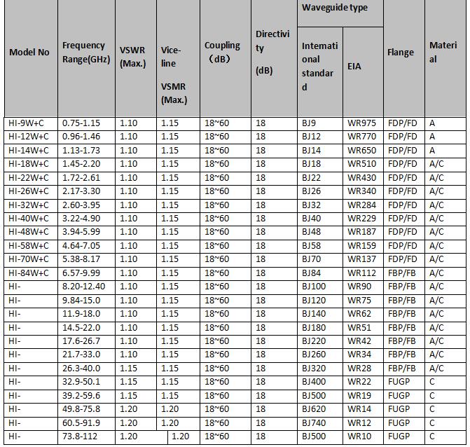
| Model No | Frequency Range(GHz) |
VSWR (Max.) |
Vice-line VSMR (Max.) | Coupling(dB) | Directivity (dB) | Waveguide type | Flange | Material | |
| International standard | EIA | ||||||||
HI-9W+C | 0.75-1.15 | 1.10 | 1.15 | 18~60 | 18 | BJ9 | WR975 | FDP/FDM | A | |
HI-12W+C | 0.96-1.46 | 1.10 | 1.15 | 18~60 | 18 | BJ12 | WR770 | FDP/FDM | A | |
HI-14W+C | 1.13-1.73 | 1.10 | 1.15 | 18~60 | 18 | BJ14 | WR650 | FDP/FDM | A | |
HI-18W+C | 1.45-2.20 | 1.10 | 1.15 | 18~60 | 18 | BJ18 | WR510 | FDP/FDM | A/C | |
HI-22W+C | 1.72-2.61 | 1.10 | 1.15 | 18~60 | 18 | BJ22 | WR430 | FDP/FDM | A/C | |
HI-26W+C | 2.17-3.30 | 1.10 | 1.15 | 18~60 | 18 | BJ26 | WR340 | FDP/FDM | A/C | |
HI-32W+C | 2.60-3.95 | 1.10 | 1.15 | 18~60 | 18 | BJ32 | WR284 | FDP/FDM | A/C | |
HI-40W+C | 3.22-4.90 | 1.10 | 1.15 | 18~60 | 18 | BJ40 | WR229 | FDP/FDM | A/C | |
HI-48W+C | 3.94-5.99 | 1.10 | 1.15 | 18~60 | 18 | BJ48 | WR187 | FDP/FDM | A/C | |
HI-58W+C | 4.64-7.05 | 1.10 | 1.15 | 18~60 | 18 | BJ58 | WR159 | FDP/FDM | A/C | |
HI-70W+C | 5.38-8.17 | 1.10 | 1.15 | 18~60 | 18 | BJ70 | WR137 | FDP/FDM | A/C | |
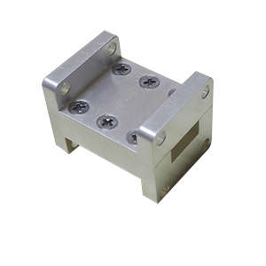
Waveguide Branch Coupler
【FEATURES】 | 【APPLICATIONS】 |
※ High Performance | ※ Communication System |
※ Low VSWR | ※ Radar System |
※ Full bandwidth of the waveguide | ※ Microwave Measurement System |
Coaxial connector type
N=N-K NJ=N-J S=SMA-K SJ=SMA-J TNC=TNC-K TNCJ=TNC-J
BNC=BNC-K BNCJ=BNC-J K=K2.92-K KJ=k2.92-J V=V2.4-K VJ=V2.4-J L16=L16-K L16J=L16-J L29=L29-K L29J=L29-J
Flange Type: Standard rectangular waveguide coaxial converter common flange type table.
Waveguide Model | P | M | E | U |
BJ3 ~ BJ70 | FDP | FDM | / | / |
BJ84 ~ BJ320 | FBP | FBM | FBE | / |
BJ400 ~ BJ500 | / | / |
| FUGP |
【DATA SHEET】
Model No | Frequency Range(GHz) | Mainline Standing(Max.) | Vice-line standing(Max.) | Coupling X(dB) | Directivity (dB)Min. | Average Power(W) | Peak Power (KW) | Waveguide type |
HI-32WBGC5.5T | 3.05-3.45 | 1.15 | 1.15 | 5.5±0.3dB | 20 | 2K | 200 | WR284 |
Waveguide Bridge Coupler
【FEATURES】 | 【APPLICATIONS】 |
※ High Performance | ※ Communication system |
※ Low VSWR | ※ Radar system |
※ Full bandwidth of the waveguide | ※ Microwave Measurement System |
【PRODUCT TYPE】
Code | Description |
WSC3 | WSC3 bridge waveguide coupler |
WSUC3 | WSUC3 bridge waveguide coupler (U type) |
WSXC3 | WSXC3 bridge waveguide coupler (X type) |
Coaxial connector type
N=N-K NJ=N-J S=SMA-K SJ=SMA-J TNC=TNC-K TNCJ=TNC-J
BNC=BNC-K BNCJ=BNC-J K=K2.92-K KJ=k2.92-J V=V2.4-K VJ=V2.4-J L16=L16-K L16J=L16-J L29=L29-K L29J=L2
Flange Type: Standard rectangular waveguide coaxial converter common flange type table.
Waveguide Model | P | M | E | U |
BJ3 ~ BJ70 | FDP | FDM | / | / |
BJ84 ~ BJ320 | FBP | FBM | FBE | / |
BJ400 ~ BJ500 | / | / |
| FUGP |
Material: A=Aluminum B=Brass C=Copper
【DATA SHEET】
Product Type | Frequency Range(GHz) | VSWR (Max.) | Coupling(dB) | Waveguide Type | Flange | Material` | |
International Standard | EIA | ||||||
HI-40WSC3 | 3.22-4.90 | 1.25 | 3 | BJ40 | WR229 | FDP/FDM | A/C |
HI-40WSUC3 | 3.22-4.90 | 1.25 | 3 | BJ40 | WR229 | FDP/FDM | A/C |
HI-40WSXC3 | 3.22-4.90 | 1.25 | 3 | BJ40 | WR229 | FDP/FDM | A/C |
HI-48WSC3 | 3.94-5.99 | 1.25 | 3 | BJ48 | WR187 | FDP/FDM | A/C |
HI-48WSUC3 | 3.94-5.99 | 1.25 | 3 | BJ48 | WR187 | FDP/FDM | A/C |
HI-48WSXC3 | 3.94-5.99 | 1.25 | 3 | BJ48 | WR187 | FDP/FDM | A/C |
HI-58WSC3 | 4.64-7.05 | 1.25 | 3 | BJ58 | WR159 | FDP/FDM | A/C |
HI-58WSUC3 | 4.64-7.05 | 1.25 | 3 | BJ58 | WR159 | FDP/FDM | A/C |
HI-58WSXC3 | 4.64-7.05 | 1.25 | 3 | BJ58 | WR159 | FDP/FDM | A/C |
HI-70WSC3 | 5.38-8.17 | 1.25 | 3 | BJ70 | WR137 | FDP/FDM | A/C |
HI-70WSUC3 | 5.38-8.17 | 1.25 | 3 | BJ70 | WR137 | FDP/FDM | A/C |
HI-70WSXC3 | 5.38-8.17 | 1.25 | 3 | BJ70 | WR137 | FDP/FDM | A/C |
HI-84WSC3 | 6.57-9.99 | 1.25 | 3 | BJ84 | WR112 | FBP/FBM/FBE | A/C |
HI-84WSUC3 | 6.57-9.99 | 1.25 | 3 | BJ84 | WR112 | FBP/FBM/FBE | A/C |
HI-84WSXC3 | 6.57-9.99 | 1.25 | 3 | BJ84 | WR112 | FBP/FBM/FBE | A/C |
HI-100WSC3 | 8.20-12.40 | 1.25 | 3 | BJ100 | WR90 | FBP/FBM/FBE | A/C |
HI-100WSUC3 | 8.20-12.40 | 1.25 | 3 | BJ100 | WR90 | FBP/FBM/FBE | A/C |
HI-100WSXC3 | 8.20-12.40 | 1.25 | 3 | BJ100 | WR90 | FBP/FBM/FBE | A/C |
HI-120WSC3 | 9.84-15.0 | 1.25 | 3 | BJ120 | WR75 | FBP/FBM/FBE | A/C |
HI-120WSUC3 | 9.84-15.0 | 1.25 | 3 | BJ120 | WR75 | FBP/FBM/FBE | A/C |
HI-120WSXC3 | 9.84-15.0 | 1.25 | 3 | BJ120 | WR75 | FBP/FBM/FBE | A/C |
HI-140WSC3 | 11.9-18.0 | 1.25 | 3 | BJ140 | WR62 | FBP/FBM/FBE | A/C |
HI-140WSUC3 | 11.9-18.0 | 1.25 | 3 | BJ140 | WR62 | FBP/FBM/FBE | A/C |
HI-140WSXC3 | 11.9-18.0 | 1.25 | 3 | BJ140 | WR62 | FBP/FBM/FBE | A/C |
HI-180WSC3 | 14.5-22.0 | 1.25 | 3 | BJ180 | WR51 | FBP/FBM/FBE | A/C |
HI-180WSUC3 | 14.5-22.0 | 1.25 | 3 | BJ180 | WR51 | FBP/FBM/FBE | A/C |
HI-180WSXC3 | 14.5-22.0 | 1.25 | 3 | BJ180 | WR51 | FBP/FBM/FBE | A/C |
HI-220WSC3 | 17.6-26.7 | 1.25 | 3 | BJ220 | WR42 | FBP/FBM/FBE | A/C |
HI-220WSUC3 | 17.6-26.7 | 1.25 | 3 | BJ220 | WR42 | FBP/FBM/FBE | A/C |
HI-220WSXC3 | 17.6-26.7 | 1.25 | 3 | BJ220 | WR42 | FBP/FBM/FBE | A/C |
HI-260WSC3 | 21.7-33.0 | 1.25 | 3 | BJ260 | WR34 | FBP/FBM/FBE | A/C |
HI-260WSUC3 | 21.7-33.0 | 1.25 | 3 | BJ260 | WR34 | FBP/FBM/FBE | A/C |
HI-260WSXC3 | 21.7-33.0 | 1.25 | 3 | BJ260 | WR34 | FBP/FBM/FBE | A/C |
HI-320WSC3 | 26.3-40.0 | 1.25 | 3 | BJ320 | WR28 | FBP/FBM/FBE | A/C |
HI-320WSUC3 | 26.3-40.0 | 1.25 | 3 | BJ320 | WR28 | FBP/FBM/FBE | A/C |
HI-320WSXC3 | 26.3-40.0 | 1.25 | 3 | BJ320 | WR28 | FBP/FBM/FBE | A/C |
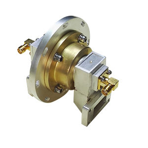
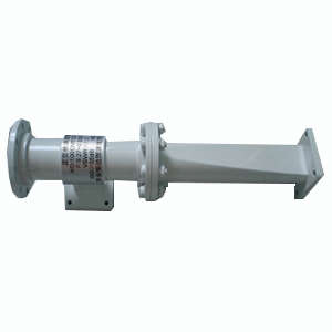
Waveguide Probe Microwave Coupler
【PRODUCT DESCRIPTION】
Circular waveguide probe coupler for circular waveguide measurement system of the circular waveguide coupled to a weak electric field to measure the deflection of circular waveguide polarization or circular polarization axial ratio. To the circular waveguide minimum field disturbance, coupling should be more than 25dB. While coupling holes and coupling probe circumferentially uniform. When measuring, a measuring probe access systems, other probes session matched load.
Material: A=Aluminum B=Brass C=Copper
【DATA SHEET】
Product Model | Frequency Range (GHz) | VSWR (Max.) | Coupling | Circular waveguide diameter (mm) | Connection Type | Material |
HI-7.137CWTC30S | 27.5~31 | 1.1 | 30dB | 7.137 | SMA-50K | C |
HI-11CWTC30S | 17.7~21.2 | 1.1 | 30dB | 11 | SMA-50K | C |
HI-11.25CWTC30S | 18.2~24.9 | 1.1 | 30dB | 11.25 | SMA-50K | C |
HI-14CWTC30S | 15.0~17.0 | 1.1 | 30dB | 14 | SMA-50K | C |
HI-20.244CWTC30S | 8.5~10.5 | 1.1 | 30dB | 20.244 | SMA-50K | A |
HI-23.825CWTC30S | 9.1~10.0 | 1.1 | 30dB | 23.825 | SMA-50K | A |
HI-27.78CWTC30S | 7.4~9.0 | 1.1 | 30dB | 27.78 | SMA-50K | A |
HI-37CWTC30N | 4.5~6.5 | 1.1 | 30dB | 37 | N-50K | A |
HI-51.99CWTC30N | 3.89~5.33 | 1.1 | 30dB | 51.99 | N-50K | A |
HI-61.04CWTC30N | 3.3~3.8 | 1.1 | 30dB | 61.04 | N-50K | A |
HI-100CWTC30N | 2.0~4.0 | 1.1 | 30dB | 100 | N-50K | A |
Circular Waveguide Probe Coupler
【PRODUCT DESCRIPTION】
Circular waveguide probe coupler for circular waveguide measurement system of the circular waveguide coupled to a weak electric field to measure the deflection of circular waveguide polarization or circular polarization axial ratio. To the circular waveguide minimum field disturbance, coupling should be more than 25dB. While coupling holes and coupling probe circumferentially uniform. When measuring, a measuring probe access systems, other probes session matched load.
Material: A=Aluminum B=Brass C=Copper
【DATA SHEET】
Model No | Frequency Range (GHz) | VSWR (Max.) | Coupling | Circular waveguide diameter (mm) | Connection Type | Material |
HI-7.137CWTC30S | 27.5~31 | 1.1 | 30dB | 7.137 | SMA-50K | C |
HI-11CWTC30S | 17.7~21.2 | 1.1 | 30dB | 11 | SMA-50K | C |
HI-11.25CWTC30S | 18.2~24.9 | 1.1 | 30dB | 11.25 | SMA-50K | C |
HI-14CWTC30S | 15.0~17.0 | 1.1 | 30dB | 14 | SMA-50K | C |
HI-20.244CWTC30S | 8.5~10.5 | 1.1 | 30dB | 20.244 | SMA-50K | A |
HI-23.825CWTC30S | 9.1~10.0 | 1.1 | 30dB | 23.825 | SMA-50K | A |
HI-27.78CWTC30S | 7.4~9.0 | 1.1 | 30dB | 27.78 | SMA-50K | A |
HI-37CWTC30N | 4.5~6.5 | 1.1 | 30dB | 37 | N-50K | A |
HI-51.99CWTC30N | 3.89~5.33 | 1.1 | 30dB | 51.99 | N-50K | A |
HI-61.04CWTC30N | 3.3~3.8 | 1.1 | 30dB | 61.04 | N-50K | A |
HI-100CWTC30N | 2.0~4.0 | 1.1 | 30dB | 100 | N-50K | A |
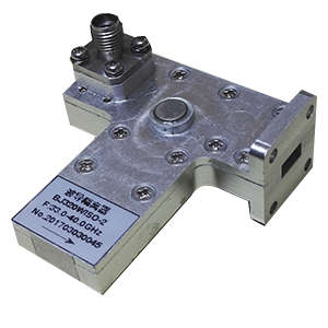
Double Ridged Waveguide High Directivity Coupler
【PRODUCT DESCRIPTION】
Description: Double Ridge Waveguide high double - ridge waveguide directional coupler is an important reflection measurement devices, commonly used in reflection measurement reflectometer. In order to improve the measurement accuracy, whether it is a scalar network analyzer or a vector network analyzer doing double - ridge waveguide reflection measurements, it is recommended to use the device as a reflection sampling devices.
【DATA SHEET】
Model No | Frequency Range (GHz) | Coupling Range(dB) | Frequency response (dB) | Directivity(dB) | Mainline VSWR(Max) | Waveguide Type | |
International Standard | EIA | ||||||
HI-84DRWC | 0.84-2 | 10-60 | ±2 | ≥20 | 1.15 | 24JS840 | WRD84D24 |
HI-150DRWC | 1.5-3.6 | 10-60 | ±2 | ≥20 | 1. 15 | 24JS1500 | WRD150D24 |
HI-200DRWC | 2-4.8 | 10-60 | ±2 | ≥20 | 1. 15 | 24JS2000 | WRD200D24 |
HI-250DRWC | 2.6-7.8 | 10-60 | ±2 | ≥20 | 1. 15 | 30JS2500 | WRD250D30 |
HI-350DRWC | 3.5-8.2 | 10-60 | ±2 | ≥20 | 1. 15 | 24JS3500 | WRD350D24 |
HI-475DRWC | 4.75-11 | 10-60 | ±2 | ≥20 | 1. 15 | 24JS4750 | WRD475D24 |
HI-500DRWC | 5-18 | 10-60 | ±2 | ≥20 | 1. 15 | 36JS5000 | WRD500D36 |
HI-580DRWC | 5.8-16 | 10-60 | ±2 | ≥20 | 1. 15 | 28JS5800 | WRD580D28 |
HI-650DRWC | 6.5-18 | 10-60 | ±2 | ≥20 | 1. 15 | 28JS6500 | WRD650D28 |
HI-750DRWC | 7.5-18 | 10-60 | ±2 | ≥20 | 1. 15 | 24JS7500 | WRD750D24 |
HI-700DRWC | 7-18.5 | 10-60 | ±2 | ≥20 | 1. 15 | 26JS7000 | WRD700D26 |
HI-1100DRWC | 11-26.5 | 10-60 | ±2 | ≥20 | 1. 15 | 24JS11000 | WRD1100C24 |
HI-1800DRWC | 18-40 | 10-60 | ±2 | ≥20 | 1. 15 | 24JS18000 | WRD1800C24 |
Circular Double Ridged Waveguide Coupler
【PRODUCT DESCRIPTION】
Double Ridged Waveguide Circular COUPLER for extracting a portion of the energy to monitor power, frequency and the matching of the system, or pulse shape and phase comparison of observed double - ridge waveguide system.
【DATA SHEET】
Model No | Frequency Range (GHz) | Coupling Range(dB) | frequency response (dB) | directivity(dB) | mainline VSWR(Max) | Waveguide Type | |
International Standard | EIA | ||||||
HI-84DRWC | 0.84-2 | 10-60 | ±2 | ≥20 | 1.15 | 24JS840 | WRD84D24 |
HI-150DRWC | 1.5-3.6 | 10-60 | ±2 | ≥20 | 1. 15 | 24JS1500 | WRD150D24 |
HI-200DRWC | 2-4.8 | 10-60 | ±2 | ≥20 | 1. 15 | 24JS2000 | WRD200D24 |
HI-250DRWC | 2.6-7.8 | 10-60 | ±2 | ≥20 | 1. 15 | 30JS2500 | WRD250D30 |
HI-350DRWC | 3.5-8.2 | 10-60 | ±2 | ≥20 | 1. 15 | 24JS3500 | WRD350D24 |
HI-475DRWC | 4.75-11 | 10-60 | ±2 | ≥20 | 1. 15 | 24JS4750 | WRD475D24 |
HI-500DRWC | 5-18 | 10-60 | ±2 | ≥20 | 1. 15 | 36JS5000 | WRD500D36 |
HI-580DRWC | 5.8-16 | 10-60 | ±2 | ≥20 | 1. 15 | 28JS5800 | WRD580D28 |
HI-650DRWC | 6.5-18 | 10-60 | ±2 | ≥20 | 1. 15 | 28JS6500 | WRD650D28 |
HI-750DRWC | 7.5-18 | 10-60 | ±2 | ≥20 | 1. 15 | 24JS7500 | WRD750D24 |
HI-700DRWC | 7-18.5 | 10-60 | ±2 | ≥20 | 1. 15 | 26JS7000 | WRD700D26 |
HI-1100DRWC | 11-26.5 | 10-60 | ±2 | ≥20 | 1. 15 | 24JS11000 | WRD1100C24 |
HI-1800DRWC | 18-40 | 10-60 | ±2 | ≥20 | 1. 15 | 24JS18000 | WRD1800C24 |
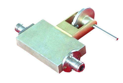
Coaxial Coupler
【PRODUCT DESCRIPTION】
coaxial couplers,
frequency range: 1-2GH, coupling: 30dB,
connector type: N type.
Coaxial connector type:
N=N-K NJ=N-J S=SMA-K SJ=SMA-J TNC=TNC-K TNCJ=TNC-J
BNC=TNC-K BNCJ=TNC-J K=K2.92-K KJ=k2.92-J V=V2.4-K VJ=V2.4-J L16=L16-K L16J=L16-J L29=L29-K L29J=L29-J
【DATA SHEET】
Model No | Frequency Range (GHz) | Coupling | Directivity |
VSWR Max. | Connector type |
HI1020CC10N | 1.0-2.0GHz | 10dB | 15dB | 1.25:1 | N |
HI1020CC20N | 1.0-2.0GHz | 20dB | 15dB | 1.25:1 | N |
HI1020CC30N | 1.0-2.0GHz | 30dB | 15dB | 1.25:1 | N |
HI2040CC10N | 2.0-4.0GHz | 10dB | 15dB | 1.25:1 | N |
HI2040CC20N | 2.0-4.0GHz | 20dB | 15dB | 1.25:1 | N |
HI2040CC30N | 2.0-4.0GHz | 30dB | 15dB | 1.25:1 | N |
HI3060CC10N | 3.0-6.0GHz | 10dB | 15dB | 1.25:1 | N |
HI3060CC20N | 3.0-6.0GHz | 20dB | 15dB | 1.25:1 | N |
HI3060CC30N | 3.0-6.0GHz | 30dB | 15dB | 1.25:1 | N |
HI4080CC10N | 4.0-8.0GHz | 10dB | 15dB | 1.25:1 | N |
HI4080CC20N | 4.0-8.0GHz | 20dB | 15dB | 1.25:1 | N |
HI4080CC30N | 4.0-8.0GHz | 30dB | 15dB | 1.25:1 | N |
HI80120CC10N | 8.0-12.0GHz | 10dB | 15dB | 1.25:1 | N |
HI80120CC20N | 8.0-12.0GHz | 20dB | 15dB | 1.25:1 | N |
HI80120CC30N | 8.0-12.0GHz | 30dB | 15dB | 1.25:1 | N |
HI80180CC10N | 8.0-18.0GHz | 10dB | 15dB | 1.25:1 | N |
HI80180CC20N | 8.0-18.0GHz | 20dB | 15dB | 1.25:1 | N |
HI80180CC30N | 8.0-18.0GHz | 30dB | 15dB | 1.25:1 | N |
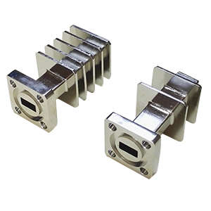
Waveguide Narrow Side Coupler
Contact us for the details.
High Directivity Directional Coupler
【FEATURES】
※ Available from 3.2G to 40G
※ Coupling from 3dB to 60dB
【DATA SHEET】
| Typical Model | HI.320WC10K |
| Freq(GHz) | 26.3-40 |
| VSWR | 1.1 |
| Insertion Loss(dB) | 0.1 |
| Coupling(dB) | 10±0.7 |
| Directivity(dB) | 35 |
Crossguide Directional Coupler
【FEATURES】
※ Available from 3.2G to 40G
※ Different interfaces can be selected,Such as waveguide,N,SMA,3.5mm,2.92mm,2.4mm
※ Standard and nonstandard flange
※ Single,dual,multiple output
【DATA SHEET】
| Typical Model | HI.320WL+3C30 |
| Freq(GHz) | 33-40 |
| VSWR | 1.1 |
| Insertion Loss(dB) | 0.1 |
| Coupling(dB) | 30±1 |
| Directivity(dB) | 20 |

